HOW TO: ANNOTATE FOUNDATION PLAN
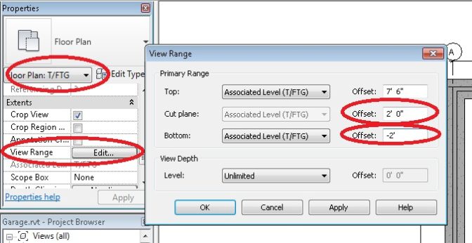
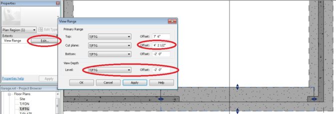
Change to the T/FTG Plan. Go into the PROPERTIES, and change the VIEW RANGE as shown (this allows us to NOT see the concrete slab, but ONLY see the FOUNDATION WALLS and FOOTINGS):
Now we want to make the FOOTING LINES out of DASHED lines. There are two ways to do this.
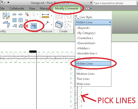
One easy way, is to go into MODIFY, and pick LINEWORK and select HIDDEN LINES. Then go pick all the lines.
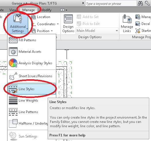
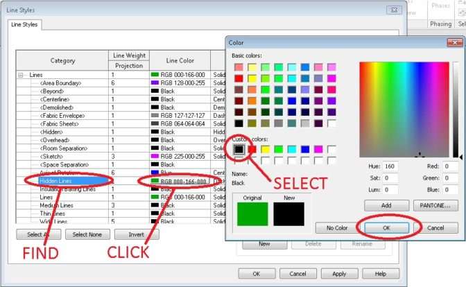
Except now our lines are green. Go to MANAGE, select SETTINGS, then ADDITIONAL SETTINGS, and pick LINE STYLES.
In there, you can change the color to BLACK
Hooray!
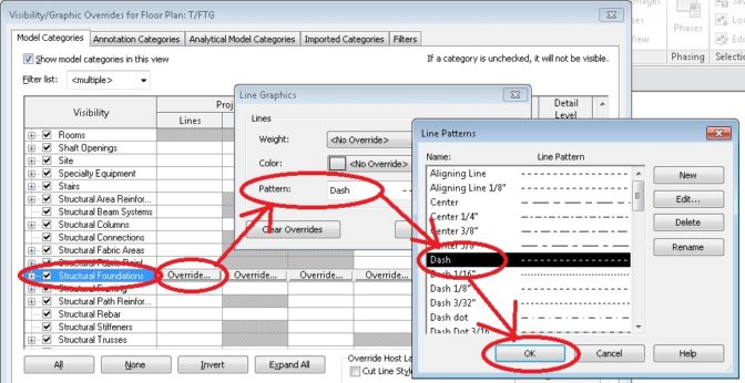
Another way is to type “VV” on your keyboard, and the VISIBILITY OVERIDE menu pops up. Change the STRUCTURAL FOUNDATIONS pattern to DASH. Wow. That was easier. Wish I had done that first.
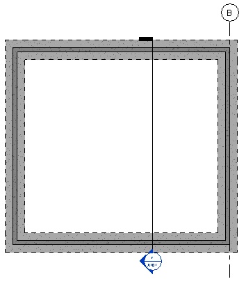
Wait a minute! Where are our GRID LINES? I only see one. How many are on your drawing?
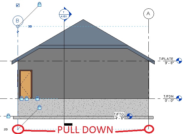
This is because we drew GRID lines before we built the foundation (T/FTG). Let’s go back to the elevation views, and drag the bottoms of the GRID LINES down below the Foundation.
Now let’s Annotate the foundation. If we have our viewing range set where it is, we might not see the details for the bottom of the roll up door. We can make that part visible by creating a PLAN REGION.
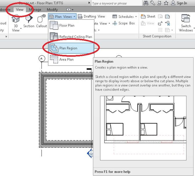
Go to VIEW and select PLAN VIEWS and then select PLAN REGION
Now, use DRAW to draw a RECTANGLE around where the Roll Up Door ought to be. I let the lines “snap” to the footings just because I felt like it.
I ended up adjusting the perimeter of this viewing area, and then I went to EDIT the VIEW RANGE (these numbers worked for the way I made the slab, yours might be different):
Now you can dimension the foundation as shown below:
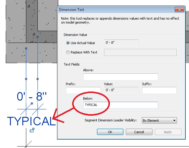
Also, dimension the width of the Foundation Wall. Double-Click it, to add TYPICAL below the dimension.
Now check how the A101 Sheet is doing. If you need to adjust anything, go to the appropriate Plan and make it VERY clear and pretty. The eagle-eyed among you will notice I went back and changed the sloped slab to actually be sloped (I had issues….).


